Impellers are deceptively difficult parts. From a distance, the geometry can look simple. In practice, helix pitch, blade continuity, cone transitions, shaft connection, symmetry, balance and surface condition all affect whether a prototype can be handled as a real engineering object.
The short answer
Exafuse can use metal 3D printing and LMD-style process development to manufacture complex impeller prototypes when a team needs a real metal part for inspection, measurement and redesign feedback before committing to a final production route.
Front view: helical geometry
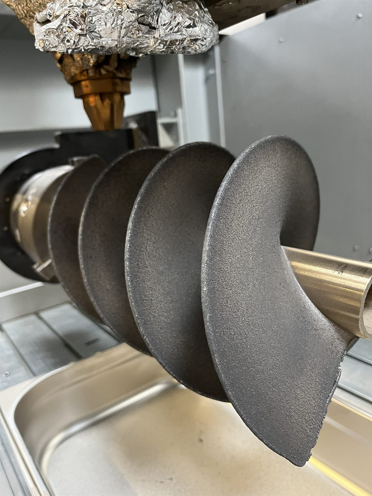
The front view makes the core challenge visible. A helical impeller is not a stack of flat blades; it is a continuous flow geometry. For prototype work, the value is that engineers can evaluate the real part instead of only reviewing CAD.
Side view: build height and blade continuity
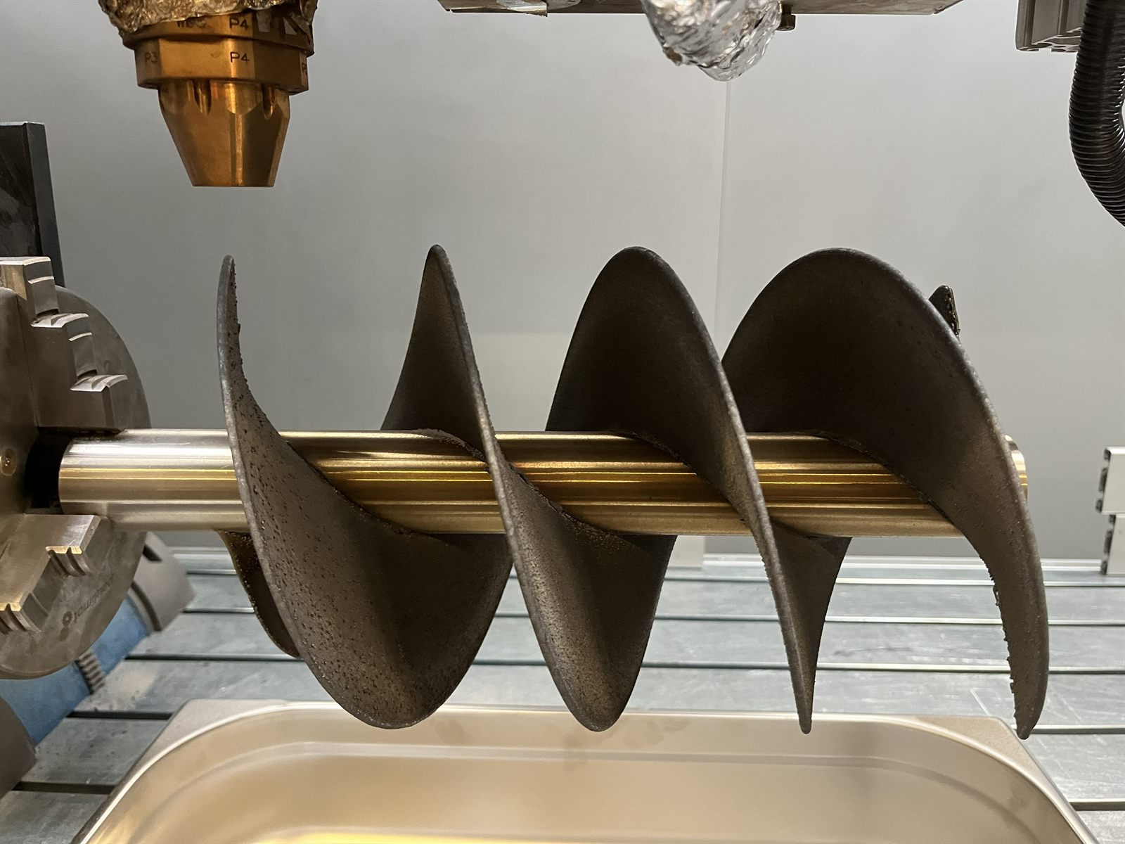
The side view shows why additive manufacturing can be useful for early impeller work. Curved surfaces, changing angles and connection details can be slow or awkward to make with conventional fabrication alone. A printed metal prototype can shorten the loop between concept, prototype, measurement and redesign.
Detail: helix-to-cone connection
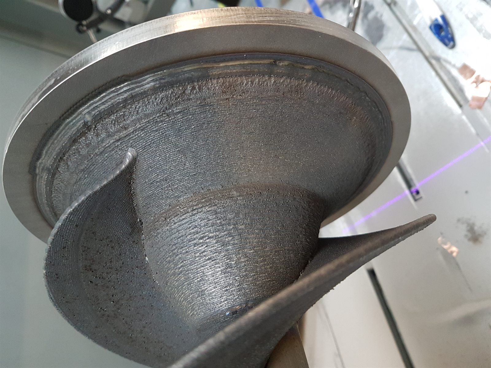
Connection details often decide whether a demonstrator is useful. The transition between blade, cone and shaft area has to support the geometry and remain accessible enough for post-processing, measurement and review.
Detail: spray-cone region
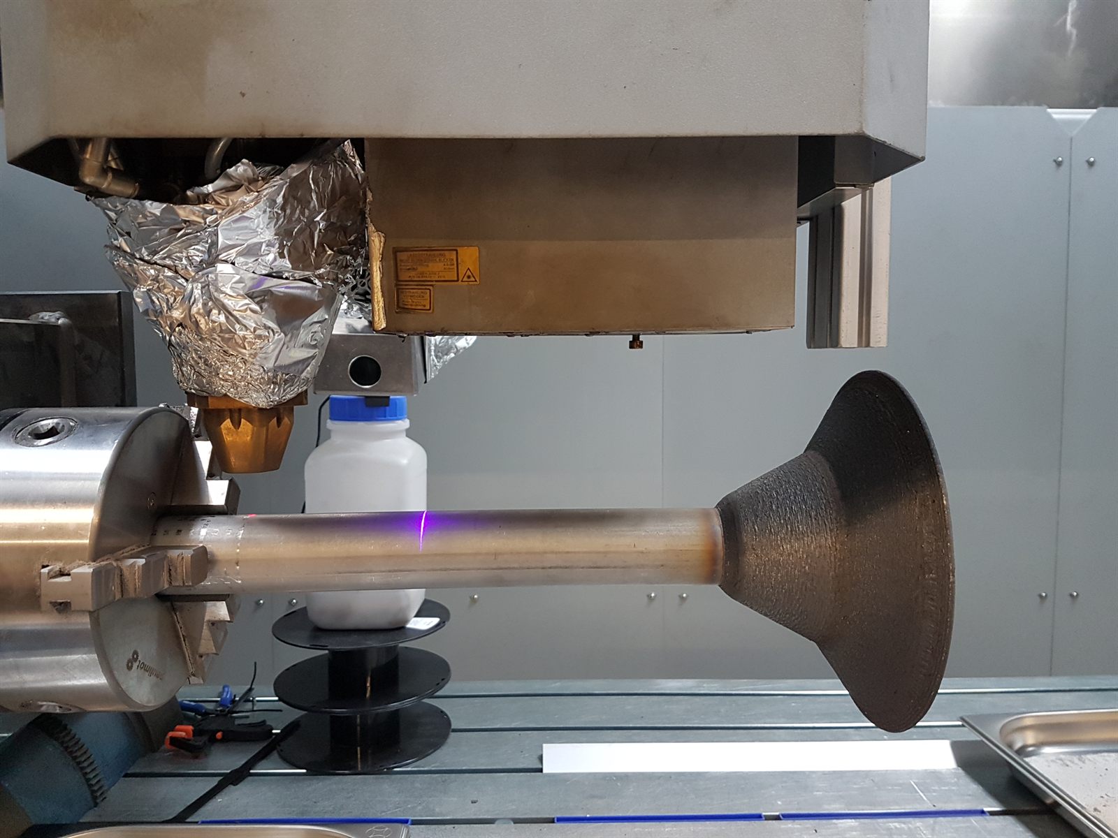
Why this matters for water-technology equipment
Water and wastewater equipment often depends on rotating components that must move fluid efficiently while surviving demanding operation. Impellers, rotors, spray cones and helical features can be hard to prototype because geometry and performance are tightly connected.
For this type of work, the value of a first printed part is speed of learning. The first prototype does not need to be final to be useful. It needs to show where geometry, interfaces, finishing, measurement and balance discussion should go next.
What had to be managed
- Translate the impeller geometry into a manufacturable build route.
- Create the helical blade structure with visible continuity.
- Manage connection zones around shaft, cone and blade features.
- Leave room for inspection, measurement and practical feedback.
- Consider balance, vibration and roundness as later review topics without publishing raw values.
- Use measurement results to improve the next design or build strategy.
Decision table
| Decision point | What it means for an impeller prototype |
|---|---|
| Prototype goal | Define whether the part must prove visual geometry, assembly fit, functional testing or a future production route. |
| Helical geometry | Blade pitch, continuity and access determine whether additive manufacturing is practical. |
| Interfaces | Shaft, hub, cone and flange areas usually need special attention for finishing, measurement and assembly. |
| Post-processing | Rotating prototypes often need machining, surface work or balancing review after the build. |
| Validation boundary | A prototype can support learning, but hydraulic performance, fatigue, corrosion and production repeatability need separate validation. |
Readable summary: evaluate metal 3D printing for impeller prototypes when complex helix geometry, fast physical feedback and hybrid post-processing create the value; escalate when final hydraulic performance, balance acceptance, material release or production repeatability must already be guaranteed.
What this proves and what it does not prove
This proof shows that a complex helical impeller concept can be converted into a physical metal prototype for visual review, measurement discussion and redesign feedback. It does not prove final hydraulic efficiency, balance acceptance, vibration limits, fatigue performance, corrosion performance, production repeatability or application release.
What to send for a similar review
- CAD model or drawings of the target geometry.
- Approximate diameter, axial length, blade count and critical interfaces.
- Material requirement or operating environment.
- Whether the goal is visual demonstrator, functional prototype or production route.
- Critical shaft, hub, cone, flange or mounting surfaces.
- Balance, vibration, measurement and inspection expectations.
- Expected post-processing, machining or surface finishing.
- Whether photos and project names may be used publicly.
Recommended next steps
Use the metal AM service page, LMD process guide, DfAM geometry article, hybrid manufacturing article, documentation and qualification guide, the Pathfinder and the manufacturing review route when planning a complex rotating-part prototype.