
When a high-value metal part fails at the working surface, the practical question is not only which coating can be applied. The stronger question is whether the substrate, coating material, heat input, dilution zone, machining allowance and inspection route can work together.
The short answer
Exafuse can treat LMD coating work as a controlled development route rather than a one-step weld overlay. In this anonymized capability context, candidate coating systems were screened on coupons, transferred toward more realistic geometry, sectioned for microscopy, reviewed with SEM/EDX and supported by Vickers HV10 hardness checks.
Why coating development needs evidence
Laser cladding is useful when the working surface carries the problem and the base component still has value. The surface may need wear resistance, corrosion resistance, sliding behavior, thermal resistance or hard-facing behavior. A coating route becomes credible when the visible surface is connected to metallurgical evidence and inspection logic, not only to a polished final photo.
What was evaluated
- Flat coating trials to compare candidate material routes.
- Transfer toward round or part-like geometry instead of stopping at flat coupons.
- Metallographic cross sections of deposited layers and substrate interfaces.
- SEM review at low and high magnification.
- EDX element mapping to understand local material distribution.
- Vickers HV10 hardness checks connected to microscopy and inspection planning.
Layer and substrate review
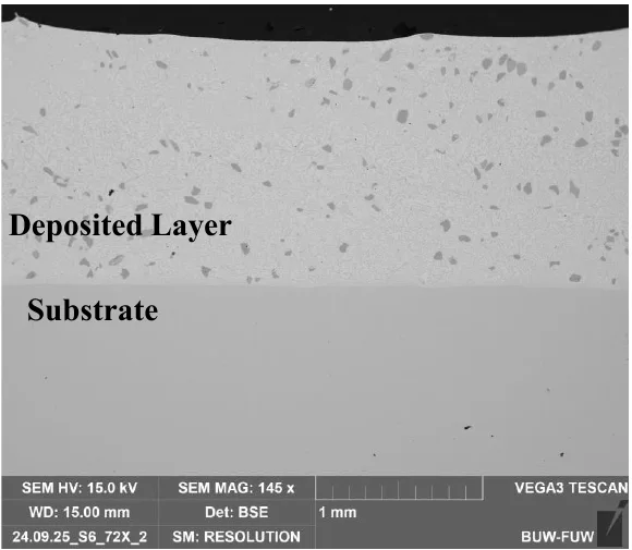
The cross section helps show whether the layer/substrate relationship can be reviewed before a coating route moves forward. The visible scope is the coating-thickness and microscopy context, not the exact customer part or machine recipe.
Microstructure and carbide distribution
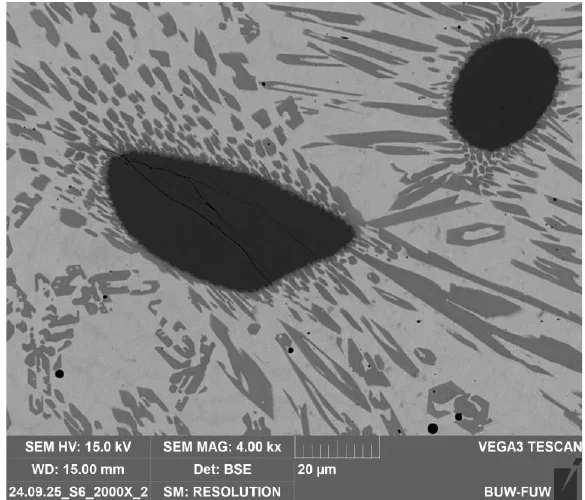
For reinforced coatings, hardness alone is not enough. Large particles, dissolved particles, local phases, pores, cracks and segregation can all change how the coating behaves after machining and in service. In the screening data, different candidate routes produced different hardness behavior, with some around the 300 HV10 class and others above 600 HV10. That shows tunability without exposing exact recipes or parameters.
EDX element mapping
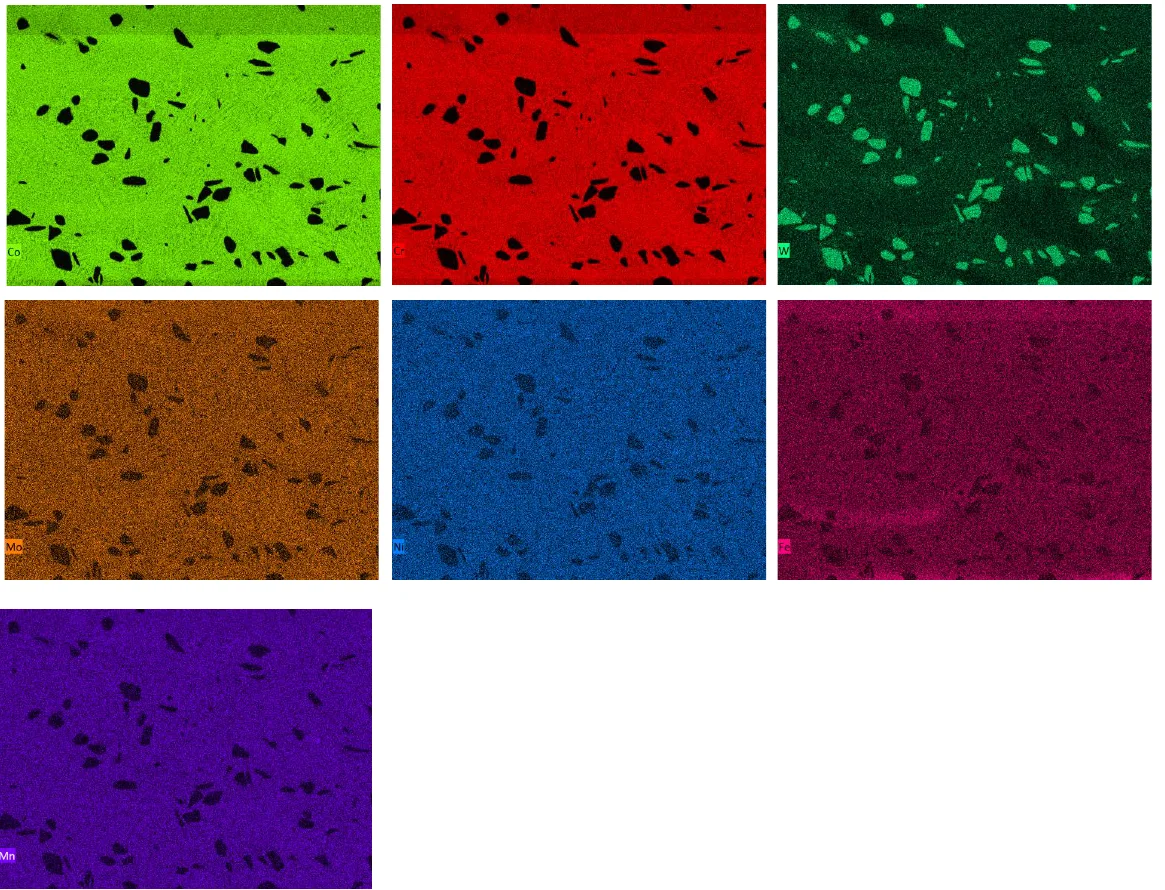
EDX mapping is useful because it connects microstructure with chemistry. The publishable message is not an exact composition table. The publishable message is that Exafuse can use SEM/EDX evidence to make coating decisions more defensible.
Vickers hardness checks
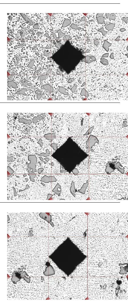
Hardness testing gives a fast read on coating behavior. It should be interpreted with layer quality, dilution, cracking risk, machining allowance and final inspection requirements. A high hardness number is not a release criterion by itself.
What this proves and what it does not prove
This proof package shows a practical Exafuse coating-development loop: screen, deposit, section, inspect, measure and decide. It does not prove universal material approval, service-life extension, final customer acceptance or feasibility for every substrate and geometry.
What to send for a similar review
- Photos, CAD, drawing or a sketch of the functional surface.
- Known base material or best available material assumption.
- Damage mode or target surface function.
- Part size, critical dimensions and allowed machining.
- Target: wear resistance, corrosion resistance, repair, replacement coating or functional upgrade.
- Tolerance, surface finish, hardness and inspection expectations.
- Confidentiality limits for photos, material names and public references.
Recommended next steps
Use the laser cladding service page, metallurgical validation guide, alloy-selection article, failure-mode map, material selector and RFQ builder when preparing a coating review.