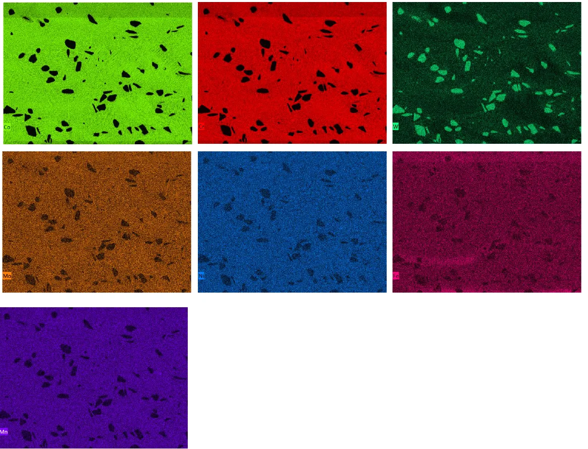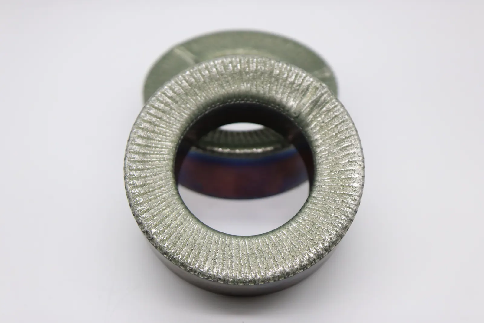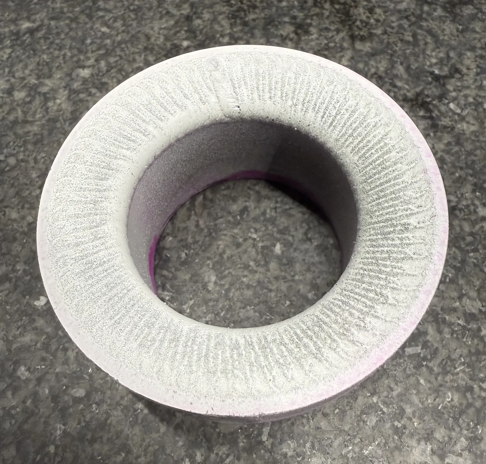
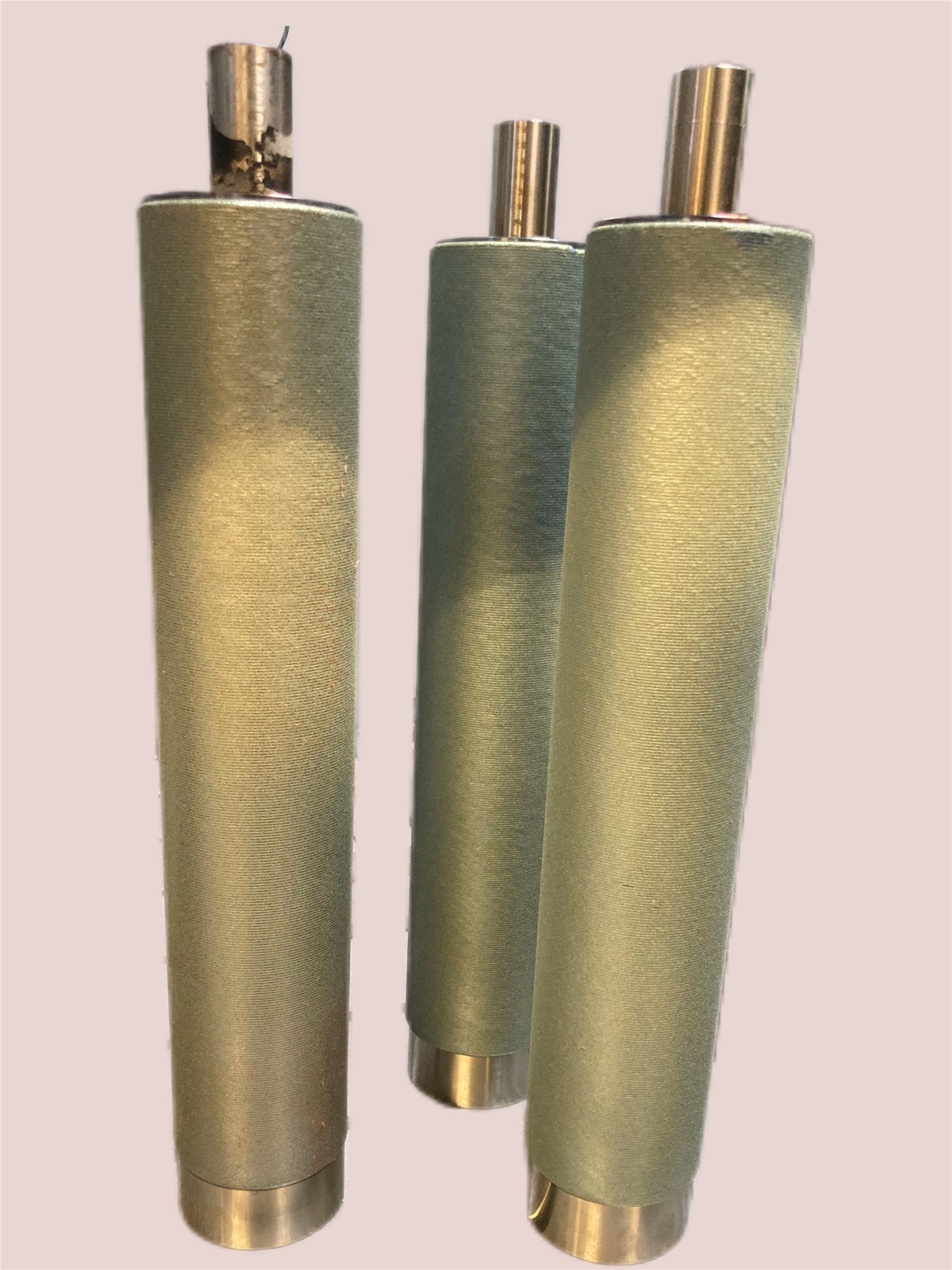
Rolling dies and cylindrical tooling concentrate value in a working surface. This case study shows how Exafuse developed a laser-cladding route for a cylindrical rolling-die component by screening coating materials, tracking diameter build-up, investigating crack and pore risk, and using metallography and hardness testing as validation context.
Case snapshot
| Component | Cylindrical rolling-die / tooling surface |
|---|---|
| Problem | Controlled surface build-up and wear-resistant coating on a rotating cylindrical geometry |
| Development route | Material screening, parameter trials, thermal strategy, diameter review, microscopy and HV1 hardness profiles |
| Material routes evaluated | Stellite 6, Stellite 12 and FeCrV15Ni6 as candidate coating routes |
| Claim boundary | Selected development evidence, not a universal production recipe |
Why the problem was technically difficult
The starting cylinder diameter was around 79 mm and the target after cladding was in the low-80 mm range. That made the job more than a surface-protection task. The coating also had to create controlled diameter build-up while still leaving a path for finishing and inspection.
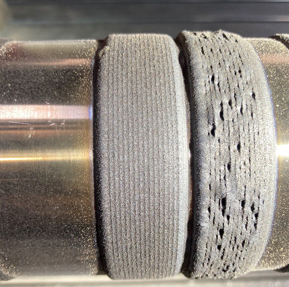
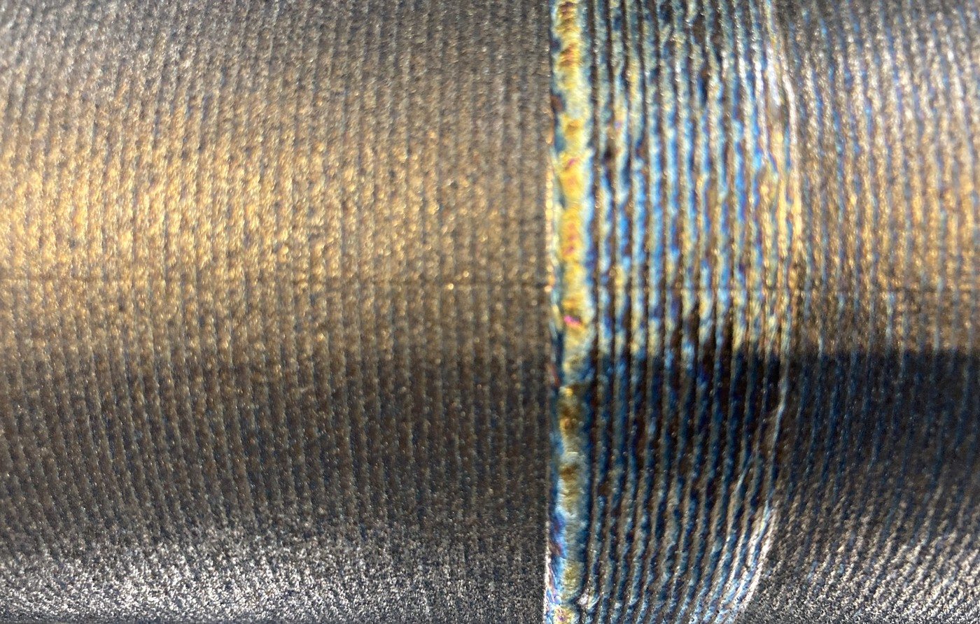
Cylindrical cladding is sensitive because the heat state changes as the part rotates and the coating progresses. Early trials showed practical issues such as powder reflection, nozzle accumulation, restart marks, pores, local cracks and diameter variation. Those are normal development questions for real cladding work.
Route selection and validation
The useful result is not a published parameter recipe. It is the development workflow: select candidate materials, run trials, inspect failure modes, adjust the setup and verify whether the new route solves the real problem.
For FeCrV15Ni6, early high-energy trials showed pore problems. Reducing energy input helped, but short samples did not automatically transfer to longer coating lengths. Later work therefore moved from sample checks toward longer coating bands. The final FeCrV15Ni6 route was described as crack-free in the selected final trial, with two pores still observed. That is a useful development result, not a blanket qualification claim.
What this proves
- Exafuse can develop laser-cladding routes for rotating cylindrical tooling, not only flat coupons.
- Material screening can compare Co-based and Fe-based hardfacing routes against surface, crack, pore and hardness behavior.
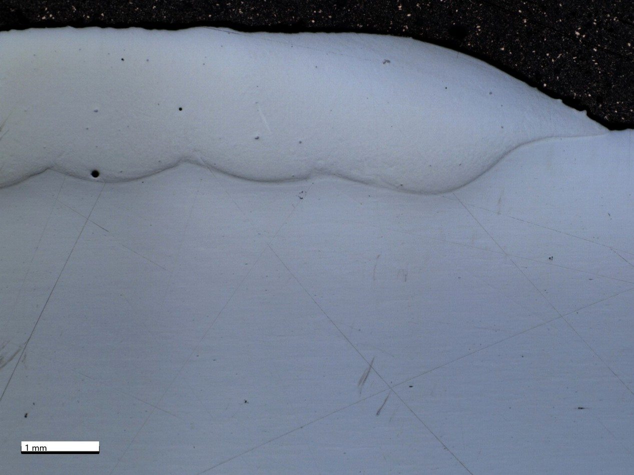
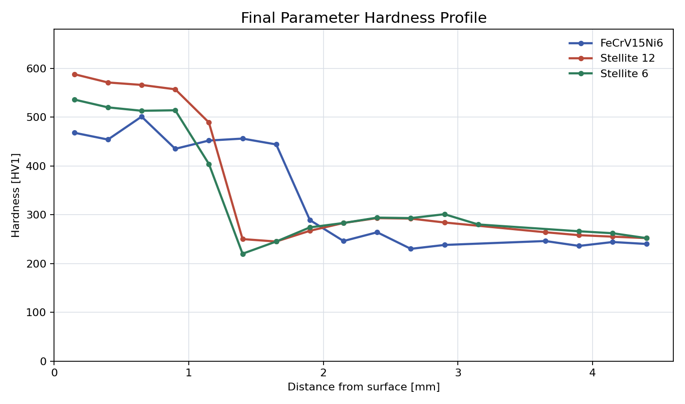
- Metallography and hardness profiles make the evidence stronger than a simple before-and-after photo.
What this does not prove
- It does not publish exact powder-feed settings, robot paths or customer drawing data.
- It does not guarantee that every rolling die, shaft or cylinder can be coated without additional development.
- It does not replace customer-specific finishing, inspection and service-acceptance criteria.
What to send for a similar cylindrical cladding review
- Part diameter, coating width and target final diameter after cladding and finishing.
- Base material, surface condition and current wear mechanism.
- Preferred coating material, hardness target or functional failure mode.
- Allowed finishing method, grinding route, roundness or runout needs.
- Inspection requirements such as cracks, pores, hardness, microscopy or documentation.
Structured case facts
| Entity | Rolling die laser cladding case study |
|---|---|
| Topic | Cylindrical LMD cladding, hardfacing, material screening, microscopy and hardness validation |
| Suitable when | Cylindrical tools where the working surface needs controlled build-up and inspection |
| Not suitable when | Unknown base material, unmanageable crack risk, inaccessible geometry or no finishing route |
| Relevant service | Laser cladding |
| Relevant tool | Material selector |
| Claim boundary | Case evidence only; a production route needs project-specific acceptance criteria. |