
Hard wear-resistant coatings are not only a powder decision. Ring geometry, substrate condition, thermal control, layer strategy, finishing allowance and inspection decide whether a laser-cladded surface is useful.
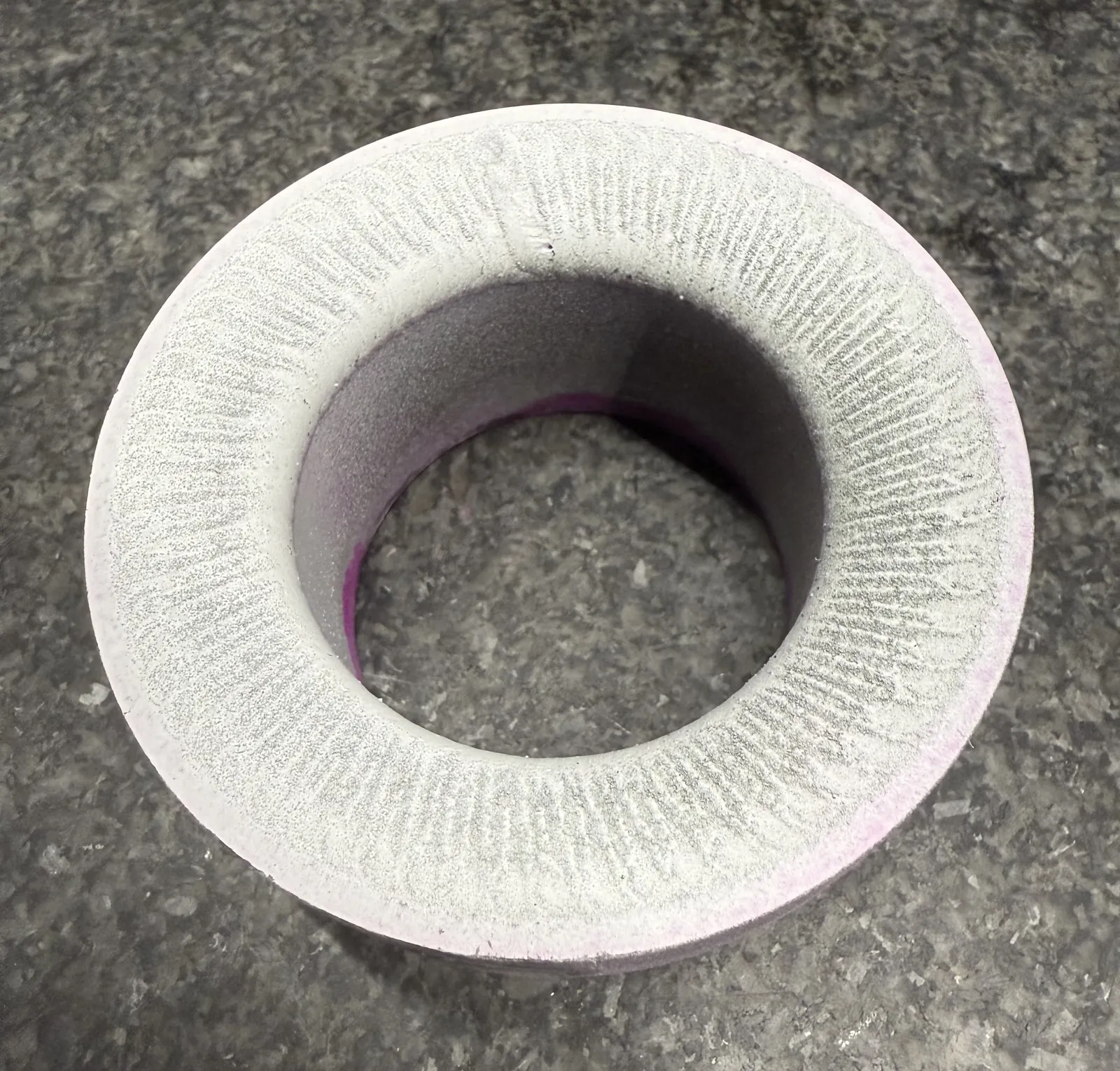
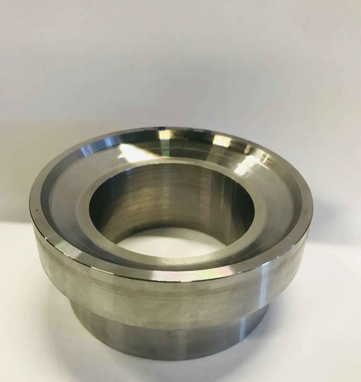
This anonymized case study covers LMD / laser cladding of a wear-resistant coating material on two ring geometries: a valve seat ring with a steep coating zone and a wear ring with a flatter groove-style coating area. The exact project material is not publicly disclosed.
Case snapshot
| Component class | Valve seat rings and wear rings |
|---|---|
| Function | Local wear-resistant working surface where the ring face or groove carries the value |
| Route | Laser Metal Deposition / laser cladding |
| Coating material | Wear-resistant coating material; exact project material not publicly disclosed |
| Valve seat geometry | Approx. 86 mm outer diameter, 55 mm inner diameter, 11 mm coating width, target coating around 2.5-3 mm |
| Wear ring geometry | Approx. 55 mm outer diameter, 33 mm inner diameter, 8.5 mm coating width, target coating around 1.5 mm |
| Main risk | Cracking and porosity from hard-material behavior, thermal stress and closing geometry |
| Process development and inspection | Controlled preheating, powder-rate and travel-speed review, layer planning, visual review and dye inspection |
Why this is a useful cladding example
Valve seat rings and wear rings concentrate value in a local working surface. Replacement is not always the only option when the technical question is whether a wear-resistant layer can be applied to the correct ring zone and then finished or inspected as required.
The case also shows the limits of simple hardness thinking. A hard coating can still be unsuitable if thermal stress, powder delivery, path closing or layer strategy are not controlled. For this reason, Exafuse treats hard cladding work as a process-chain review rather than a material-name shortcut.
Starting condition and geometry
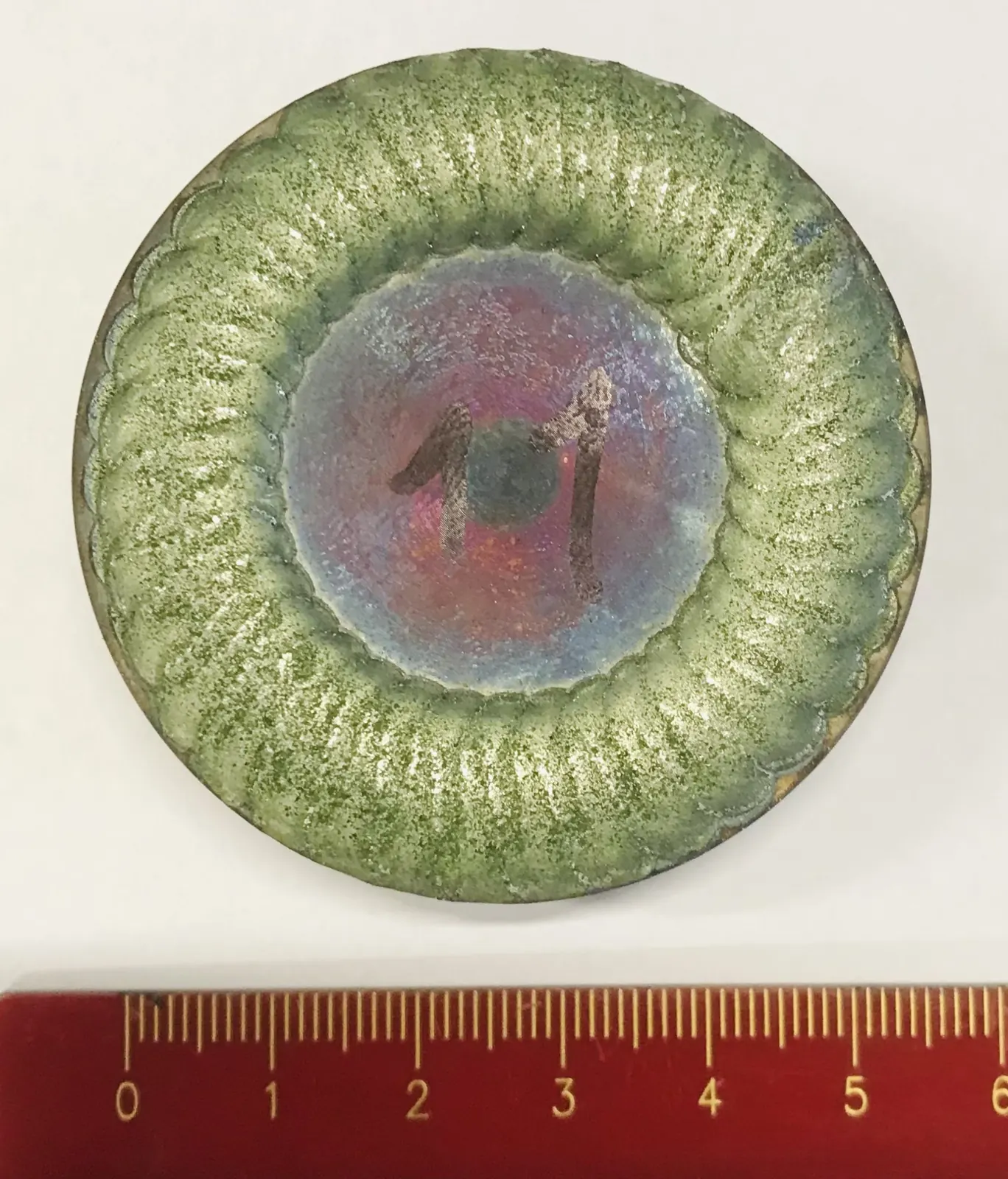
The two rings created different deposition problems. The valve seat ring required controlled deposition on a steeper coating profile. The wear ring used a flatter groove-style surface where filling and surface uniformity mattered.
Process variables reviewed
The project reports evaluated the influence of laser power, powder feed, travel speed, spot size, preheating and layer count. Exact settings are handled as controlled project data. The useful customer lesson is still clear: preheating alone did not solve crack risk. Powder rate, travel speed, layer strategy and closing behavior also changed the result.
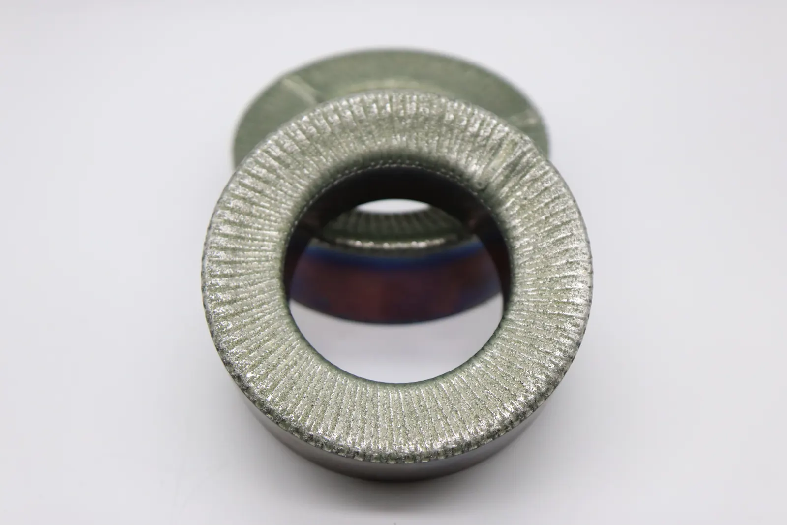
Later process-development work on the wear ring showed that a lower powder-feed direction combined with moderated deposition speed and controlled preheating could reduce visible cracking and porosity in dye testing. That is a process-development lesson, not a universal setting that can be copied onto every ring.
Dye inspection made the result visible
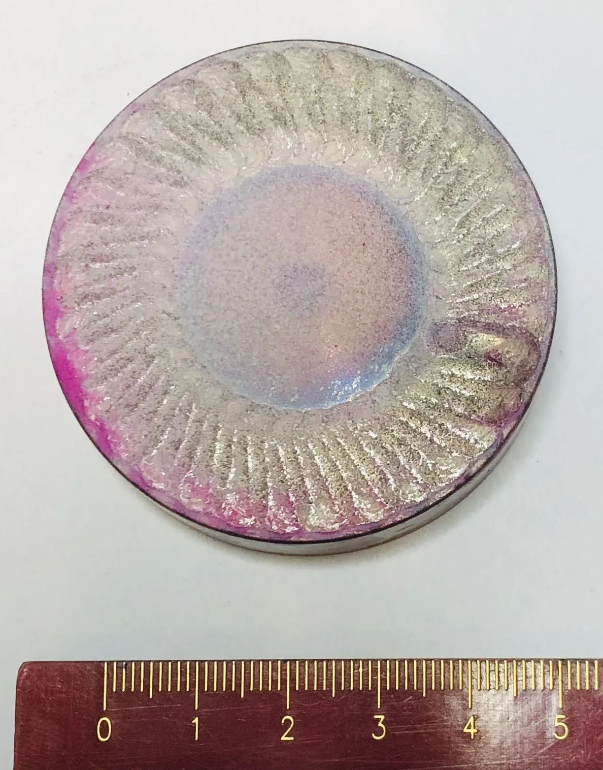
Dye penetrant inspection is valuable in this case because it turns crack and pore risk into a visible review step. In the available media, the valve seat ring and final wear-ring condition are shown after dye testing without visible cracks or pores in the photographed condition.
What buyers should send for a similar review
- Photos of the ring, working surface, groove, seat or worn zone.
- Drawing or CAD with outer diameter, inner diameter, coating width and target layer height.
- Base material and any required coating material, if already specified.
- Failure mode: sliding wear, abrasive wear, hot wear, corrosion or mixed duty.
- Required final machining, grinding, sealing surface or fit condition.
- Inspection needs such as dye testing, microscopy, dimensional check or documentation.
The right decision is not only whether a hard coating can be deposited. The useful decision is whether geometry, material, heat route, layer plan, finishing and inspection can be combined into a controlled coating workflow.
Request a cladding review or start with the material selector.