
Many cladding and repair jobs start with a surface that is not perfectly described by a clean CAD model. The surface has to be measured before a useful deposition path can be prepared.
The short answer
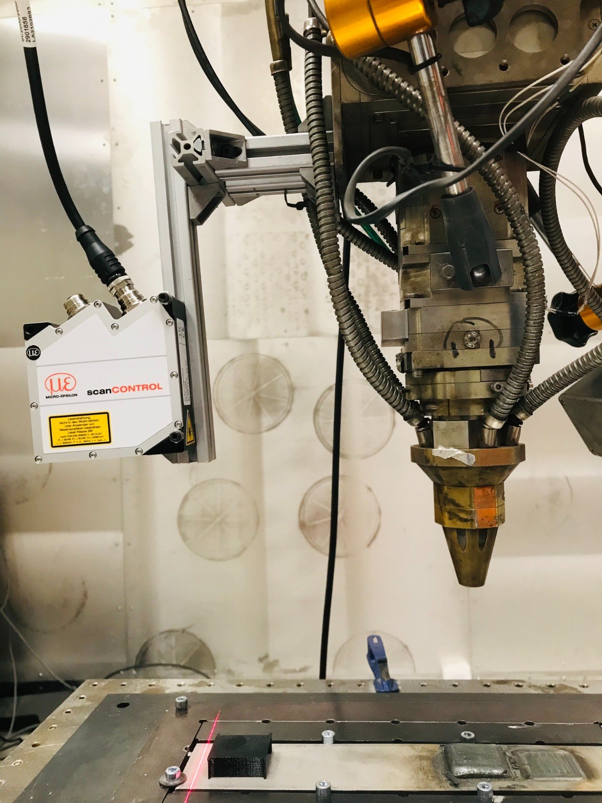
Line scanning helps Exafuse capture part profiles, compare measured geometry with the intended route and prepare contour-following LMD or laser cladding paths. The software value is practical: scan, interpret, plan and review before depositing material.
From profile to robot movement logic
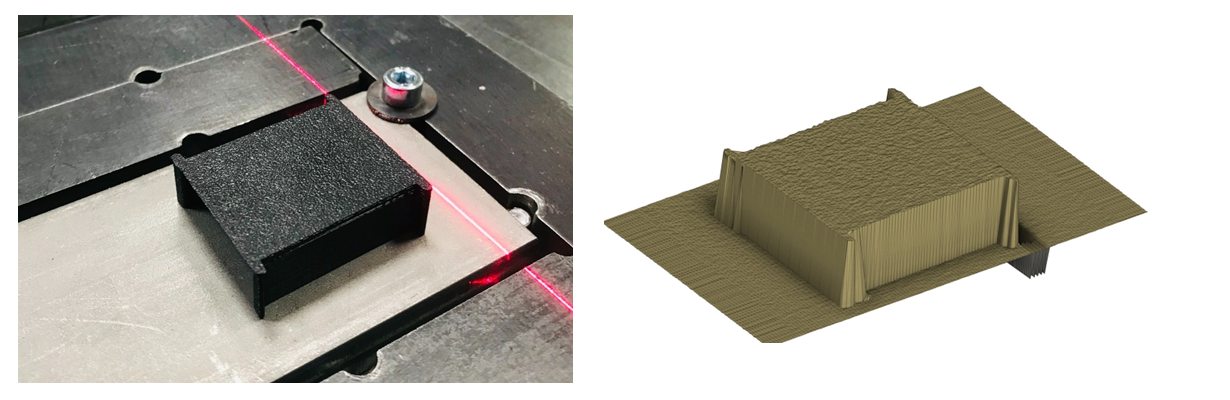
The scanner output can be used to compare measured geometry, detect surface profile, support coating offset decisions and prepare robot movement logic for a cladding route. This does not mean every scanned surface becomes an automatic production program. It means the path-planning discussion starts from measured geometry.
Decision table
| Use case | Why scanning helps |
|---|---|
| Worn or modified surface | The actual profile can differ from nominal CAD. |
| Coating on a curved part | Offset, access and tool orientation need measured geometry. |
| Robot path preparation | Measured profiles can support safer path review before deposition. |
Readable summary: scan when geometry uncertainty affects coating quality, standoff, path planning or finishing allowance.
What this proves and what it does not prove
This proves a scanner-supported development route for LMD cladding and repair. It does not publish robot code, source code, calibration data or an automatic path guarantee for every part.
What to send for a similar review
- Photos and rough dimensions of the surface.
- CAD or drawings if available.
- Target coating zone and offset direction.
- Access constraints for scanner, robot and finishing tools.
Recommended next steps
Use the laser cladding page, repair page, standoff sensing article and the cladding review route.