

One damaged journal can take the whole shaft out of service
Shafts usually lose their value in just a few places: the journal, the bearing seat, the sealing surface or the shaft end. The rest of the shaft body often remains fully serviceable. Even so, a single crack can stop the entire machine.
A new part is often expensive and rarely available at short notice. When no spare is in stock, lead time becomes the real cost driver – not the price of the repair.
Typical starting points:
- Cracked journal: cracks at the shaft end, often found during maintenance or cleaning.
- Worn bearing or seal seat: functional surfaces that have run undersize.
- Machining error: one diameter was cut too small, the rest of the part is fine.
- Worn working surface: rolls, rollers, sleeves and cylindrical tools with lost surface material.
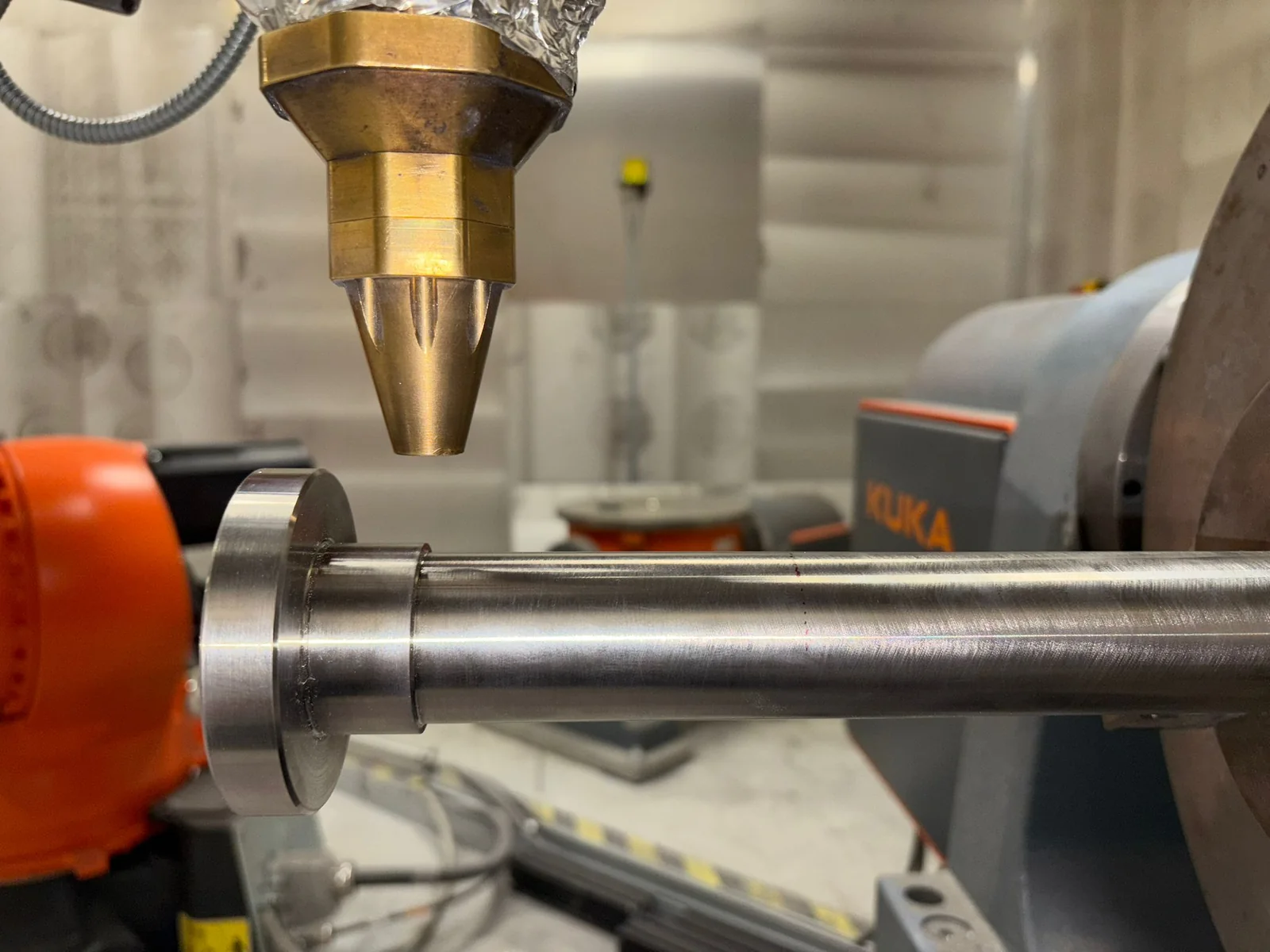
How we repair shafts with LMD
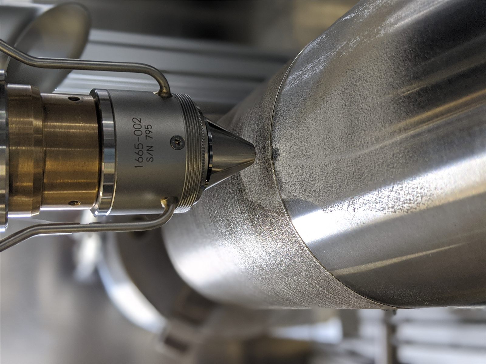
In laser metal deposition, a laser creates a small melt pool into which metal powder is fed. This produces a metallurgical bond with the base material. The rotary axes turn the shaft so that the deposited tracks run evenly around the circumference.
- Assess the damage – We review photos, drawings, dimensions, base material and service conditions, and check whether the damage is local.
- Remove the damage – Cracks and damaged material are machined away, not covered up. On the extrusion screw, we cut off the cracked shaft section completely.
- Plan the build-up – We define the deposition zone, material, machining allowance, heat management and the final machining step.
- Deposit material – Metal is built up track by track only where it is missing.
- Measure – We check the deposited diameter before final machining. On the spindle, about 1.75 mm of stock remained for machining.
- Finish and inspect – The shaft is brought back to shape, surface finish and fit, then inspected against the acceptance criteria agreed beforehand.

Materials: depending on the base material and duty, Fe-based steels, Ni-based alloys or Co-based and hard-phase systems may be suitable. Documented examples include Inconel 718 on a spindle and Stellite 6, Stellite 12 and FeCrV15Ni6 on a cylindrical tool. More on materials.

When LMD repair is not the right choice
Not every shaft should be repaired. We advise against it when
- the base material or its condition is unknown and cannot be clarified,
- the damage is systemic, for example extensive or uncontrolled cracking,
- the damaged zone cannot be reached by the laser, the powder stream or the machining tool,
- the shaft cannot be machined back to nominal size after deposition,
- a new part is available quickly and cheaply,
- the required qualification cannot be achieved.
In these cases a clear no is more credible than a speculative order. The project examples below apply to the documented part condition; for every new shaft we review material, process and acceptance separately.
Shafts and cylindrical parts from our projects
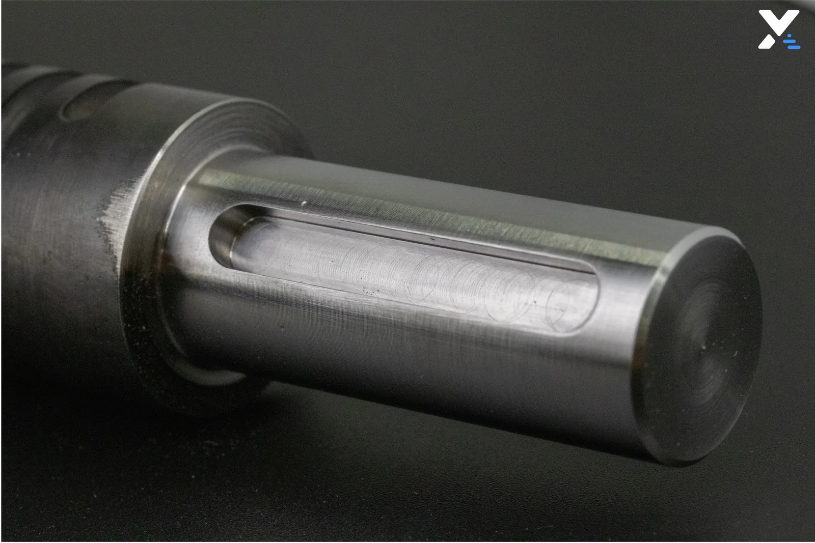
Extrusion screw: cracked stub shaft rebuilt Severe cracks on the stub shaft of a screw were found during routine cleaning of a Nobufil extrusion line. No replacement screw was available from the manufacturer at short notice. We removed the cracked section, rebuilt the geometry by LMD and finished it by milling. View the extrusion screw case study

Spindle: undersize corrected in 24 hours A spindle feature had been machined undersize. We deposited Inconel 718 over a length of 85 mm, leaving about 1.75 mm of stock for final machining. In this case the repair took 24 hours. View the spindle repair case study
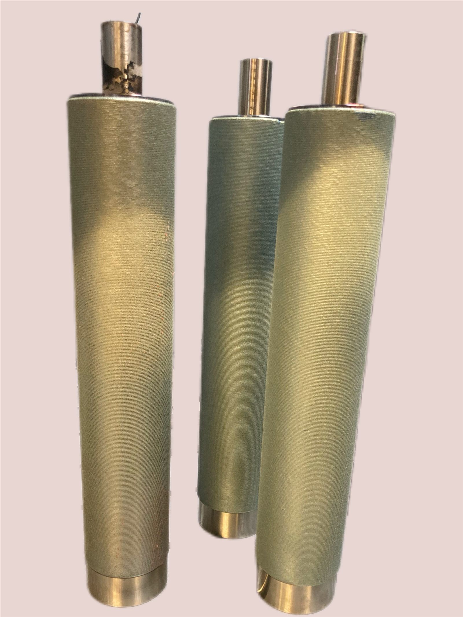
Cylindrical tool: controlled diameter build-up On a cylindrical rolling die, the diameter was built up from about 79 mm into the low 80 mm range. We compared Stellite 6, Stellite 12 and FeCrV15Ni6 and evaluated the results with metallography and HV1 hardness profiles. View the rolling die case study
More examples: All case studies
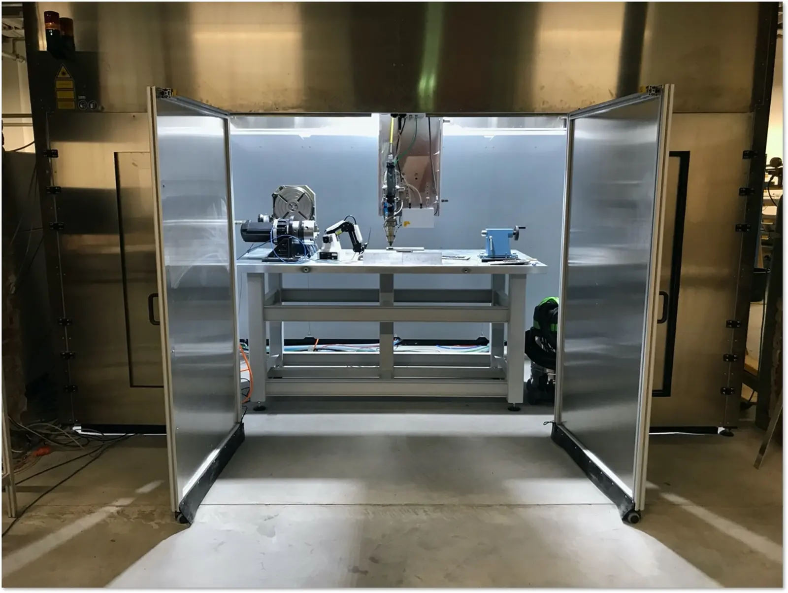
Equipment for shafts and rotationally symmetric parts
CNC-based LMD system
- Part envelope up to 2 × 1 × 2 m within a 4 m³ build space
- Additional rotary axes for continuous tracks on shafts, rolls, sleeves, bearing seats, hydraulic rods, screws and rings
- Integrated scanning for alignment, geometry capture and path referencing
- In-house sensors for process observation and height control
Robotic LMD system (developed in-house)
- Six robot axes and three positioning or rotary-table stations
- Rotary table up to 1,000 kg, approximately 4 m² of accessible working area
- For shafts with steps, flanges or hard-to-reach contours
Inspection and finishing
- Microscopy and metallographic preparation (Struers DP-U3) for cross-sections
- Milling, grinding, sandblasting and heat treatment as part of the process chain; where external specialists handle machining or inspection, we define interfaces transparently in the project scope
Full equipment details: Technology and equipment
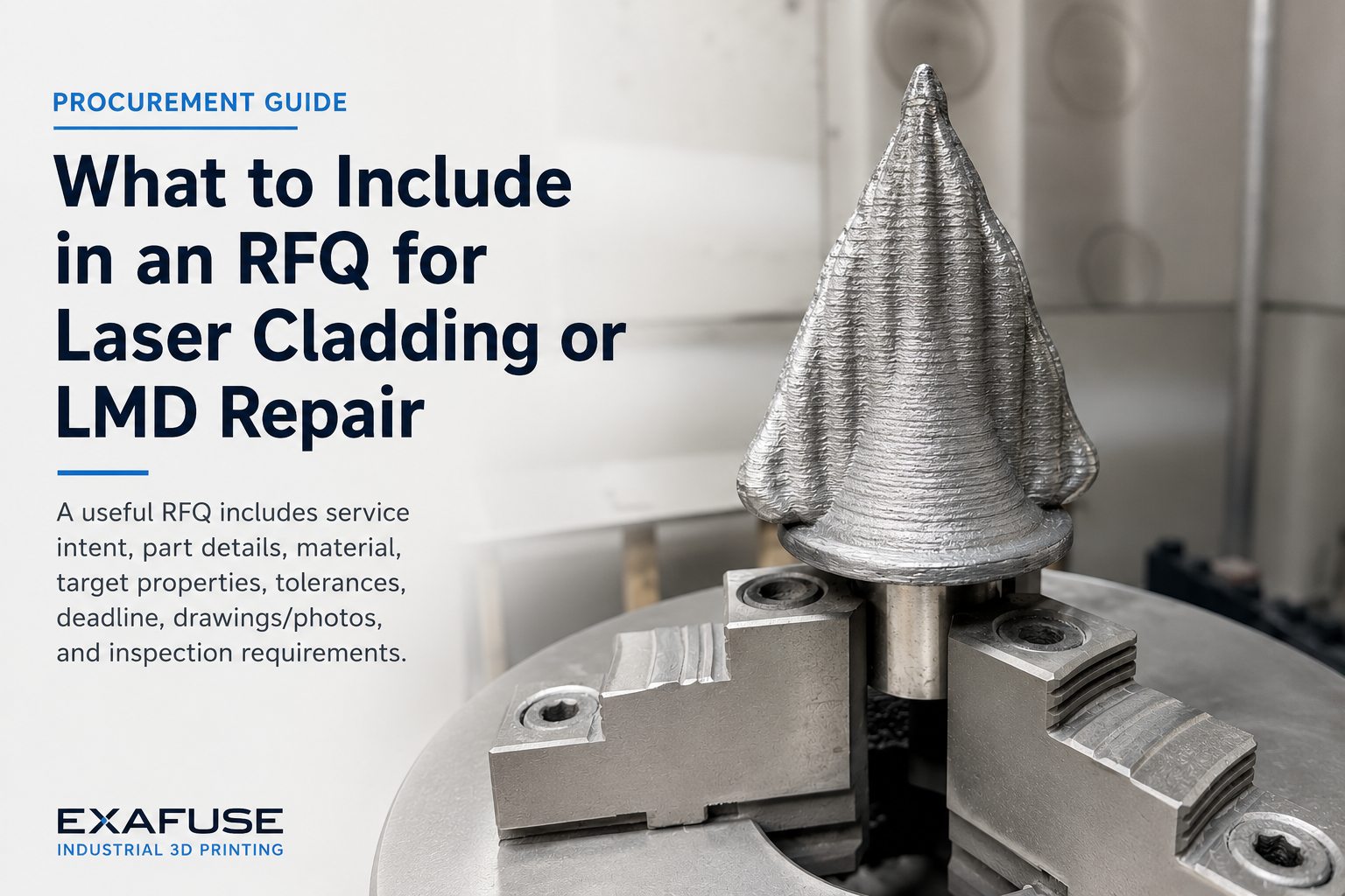
What we need for your quotation
- Photos of the damaged zone from several angles, ideally with a scale
- Drawing or CAD with nominal diameter and tolerance
- Measured actual diameter and length of the damaged zone
- Overall length, largest diameter and weight of the shaft
- Base material and heat-treatment condition, if known
- Damage pattern and service conditions
- Required surface finish, roundness or runout – and whether final machining is done by you or by us
- Deadline, shutdown window, and price and lead time of a new part
- Inspection and documentation requirements
Incomplete information is not a problem. We will tell you what is still missing. For confidential drawings, we agree an NDA and transfer method first.
Useful for preparation: RFQ Builder · Repair ROI Calculator

Frequently asked questions about shaft repair
How much does it cost to repair a shaft by LMD? There is no flat price, because every damaged zone is different. Cost depends mainly on removing the damage, deposit volume and material, fixturing, final machining, inspection and documentation. Compare the repair with a new part including downtime during its lead time – our Repair ROI Calculator helps with that.
How quickly will I hear back, and how long does the repair take? You receive an initial assessment of your enquiry within 24 hours on working days. Repair lead time depends on the extent of damage, material, finishing and inspection scope. In one documented case, the repair of an undersized spindle took 24 hours.
How large and heavy can the shaft be? The CNC-based LMD system accepts parts of up to 2 × 1 × 2 m and has additional rotary axes for shafts. The robotic system has a rotary table rated up to 1,000 kg.
Which materials can be deposited? Options include Fe-based steels, Ni-based alloys and Co-based or hard-phase systems. The base material, duty and machinability decide. Documented examples include Inconel 718 on a spindle and Stellite 6, Stellite 12 and FeCrV15Ni6 on a cylindrical tool.
How is the repaired zone inspected? We agree the inspection scope before deposition starts. Typical steps are dimensional inspection, surface and crack testing, hardness testing and cross-sections to assess bonding, dilution and microstructure. The right method depends on the function and risk of the shaft.
How does LMD differ from thermal spraying or conventional weld overlay? LMD melts metal locally and bonds it metallurgically to the base material. Thermal spraying can make sense for certain surfaces, for example thin layers on large, cost-sensitive areas. Whether replacement, conventional welding or LMD fits best is part of our feasibility check.
Have your shaft assessed
Send photos, dimensions and the base material. We will tell you whether an LMD repair is realistic and what information is still missing.
Request a feasibility check View projectsPhone: +49 234 60276628
Further reading: Repair and modification · Repair vs replace
Related applications: Turbine, pump and generator parts · Hardfacing and wear protection · All applications