LMD / DED-LB/M
Large parts, local material addition, repair and cladding
A laser creates a local melt pool while metal powder is supplied. Access, heat input, bead geometry and finishing determine suitability.
 Metal additive manufacturing
Technology
Process selection follows component function, geometry, material compatibility, finishing and inspection. No machine is the best choice for every job.
Process selection
Part size, detail, access and functional surfaces establish the initial direction. Material and inspection requirements may then change the choice.
LMD / DED-LB/M
A laser creates a local melt pool while metal powder is supplied. Access, heat input, bead geometry and finishing determine suitability.
SLM / LPBF
The component is built layer by layer in a powder bed. Orientation, supports, residual stress and post-processing belong in the initial plan.
Additive-subtractive manufacturing
On this page, “hybrid” means combining additive build-up with subtractive finishing. It does not imply that LMD and SLM/LPBF are automatically combined in one component.
Equipment and build space
The figures describe the published technical envelope. Part access, fixturing, material, finishing and inspection determine actual suitability.
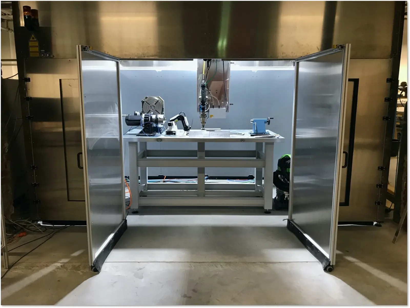
CNC-based LMD system
The published component window reaches 2 × 1 × 2 m within a 4 m³ build space. Additional rotary axes support continuous deposition around cylindrical parts.
Robotic LMD system
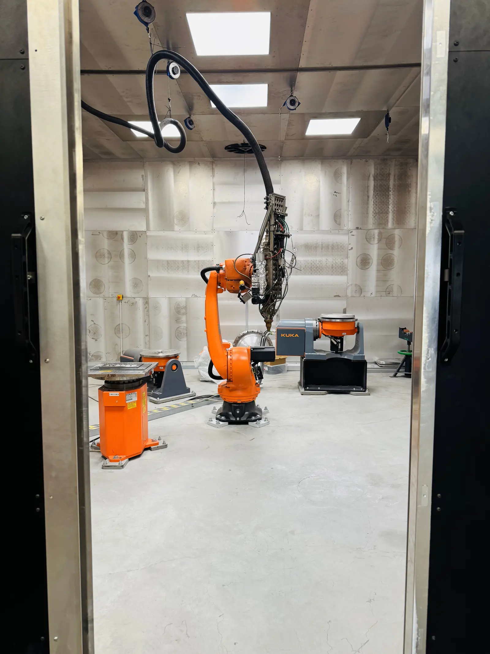
Exafuse developed the robotic cell for parts that require contour-following access, changing tool angles or additional positioning.
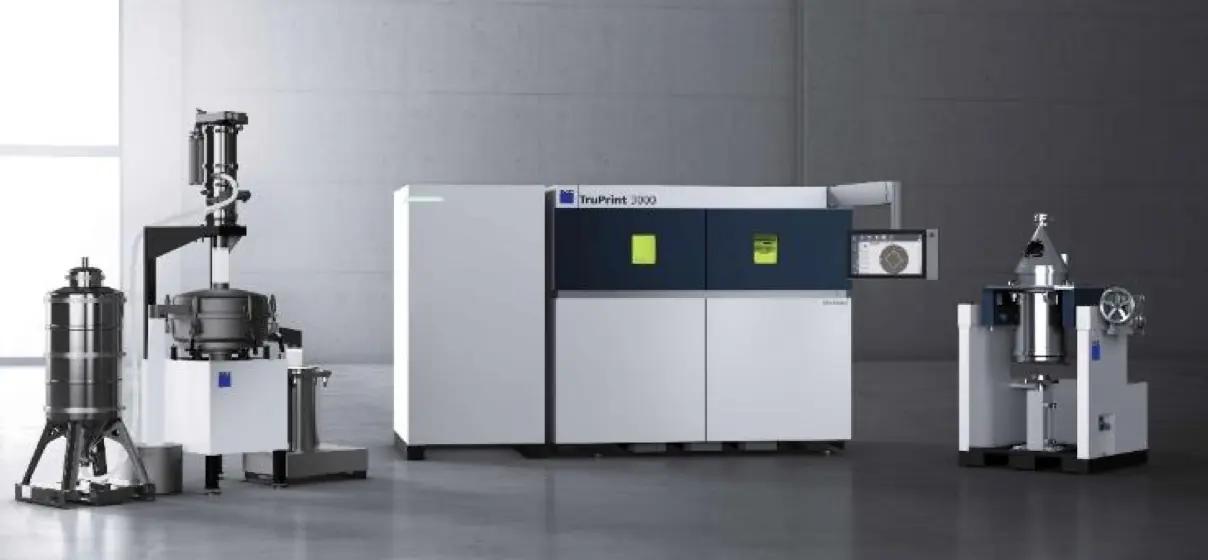
TRUMPF TruPrint 3000
SLM/LPBF with a 400 mm platform diameter, 400 mm build height and 500 W single laser for parts whose value comes from compact detail.
Scanning, sensing and monitoring systems support alignment, process observation and technical assessment. They do not replace agreed component inspection or project-specific acceptance.
Parts and special-purpose systems
Exafuse can also develop LMD machine concepts for companies and special components when standard kinematics, fixturing, scanning or process monitoring are insufficient.
Shafts, rollers, bearing seats, sleeves, hydraulic rods, screws, rings and cylindrical tooling.
Structural nodes, housings, dies, impellers, nozzles, valve bodies, curved tooling and local modifications.
Internal channels, lattices, tooling inserts, compact impellers and prototypes within the published build envelope.
Project-specific LMD cells, scanners, positioners, fixtures, sensing, monitoring, control and path planning.
Project-specific machine development
The scope may range from a component-specific fixture to a dedicated cell or machine concept. Integration, machine safety, acceptance and delivery scope are defined separately for each project.
From data to inspected component
A workable manufacturing plan connects build-up, finishing and inspection in one process chain.
Capture geometry, material, function, quantity and timing.
Compare LMD, SLM/LPBF and additive-subtractive manufacturing technically.
Define the deposition or build strategy, machining allowance, heat treatment and surface condition.
Agree inspection features, documentation and acceptance criteria before manufacture.
Project examples
The examples document specific applications. Material and acceptance requirements remain specific to each new component.
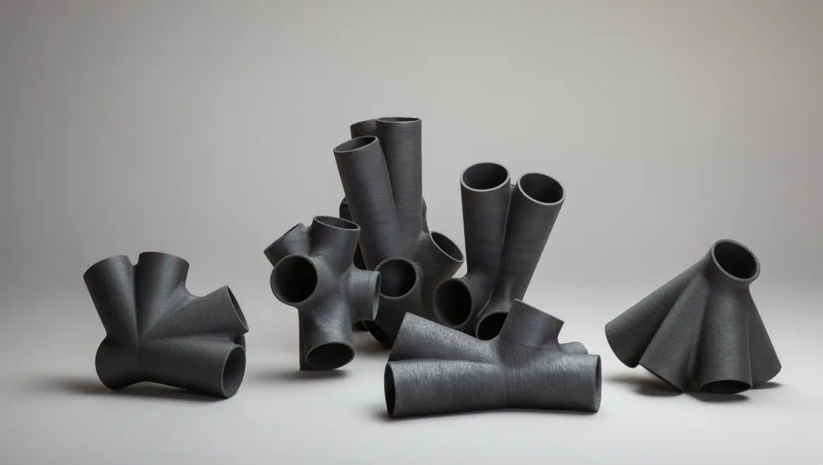
Large component
Structural nodes with CAD adaptation, robotic path planning, monitoring and project-specific validation.
View project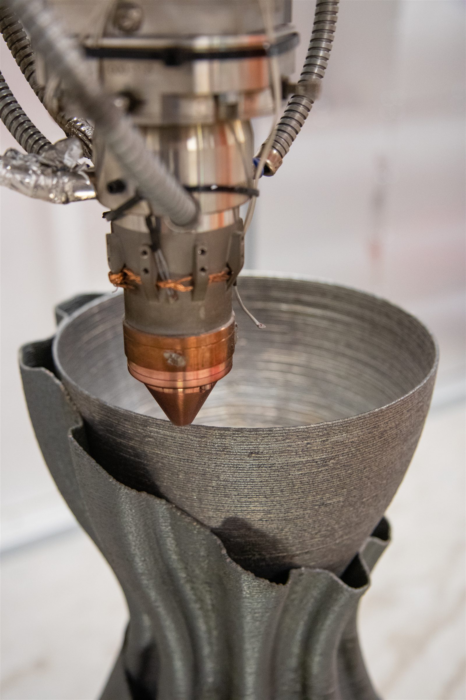
Thin-wall build
An LMD demonstrator with distinct Ni-based material zones and water-cooled geometry.
View project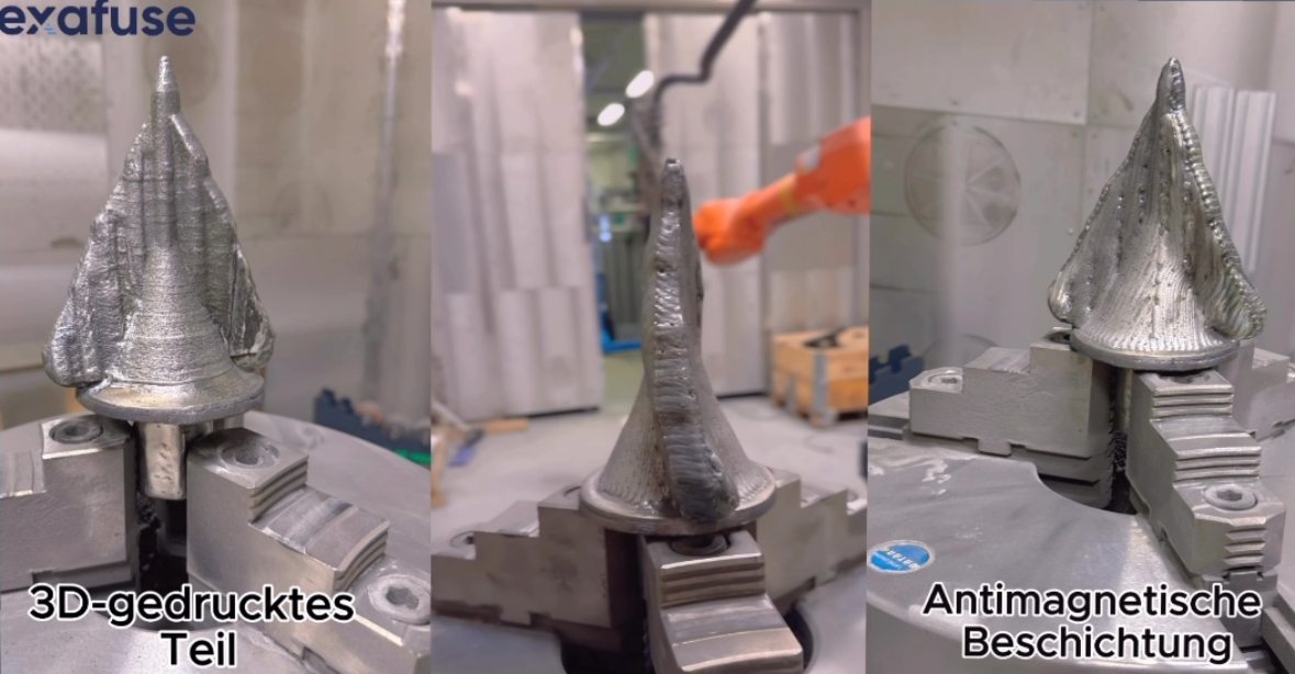
Build and coat
LMD part build-up and a tungsten-carbide-containing functional layer in one coordinated manufacturing sequence.
View project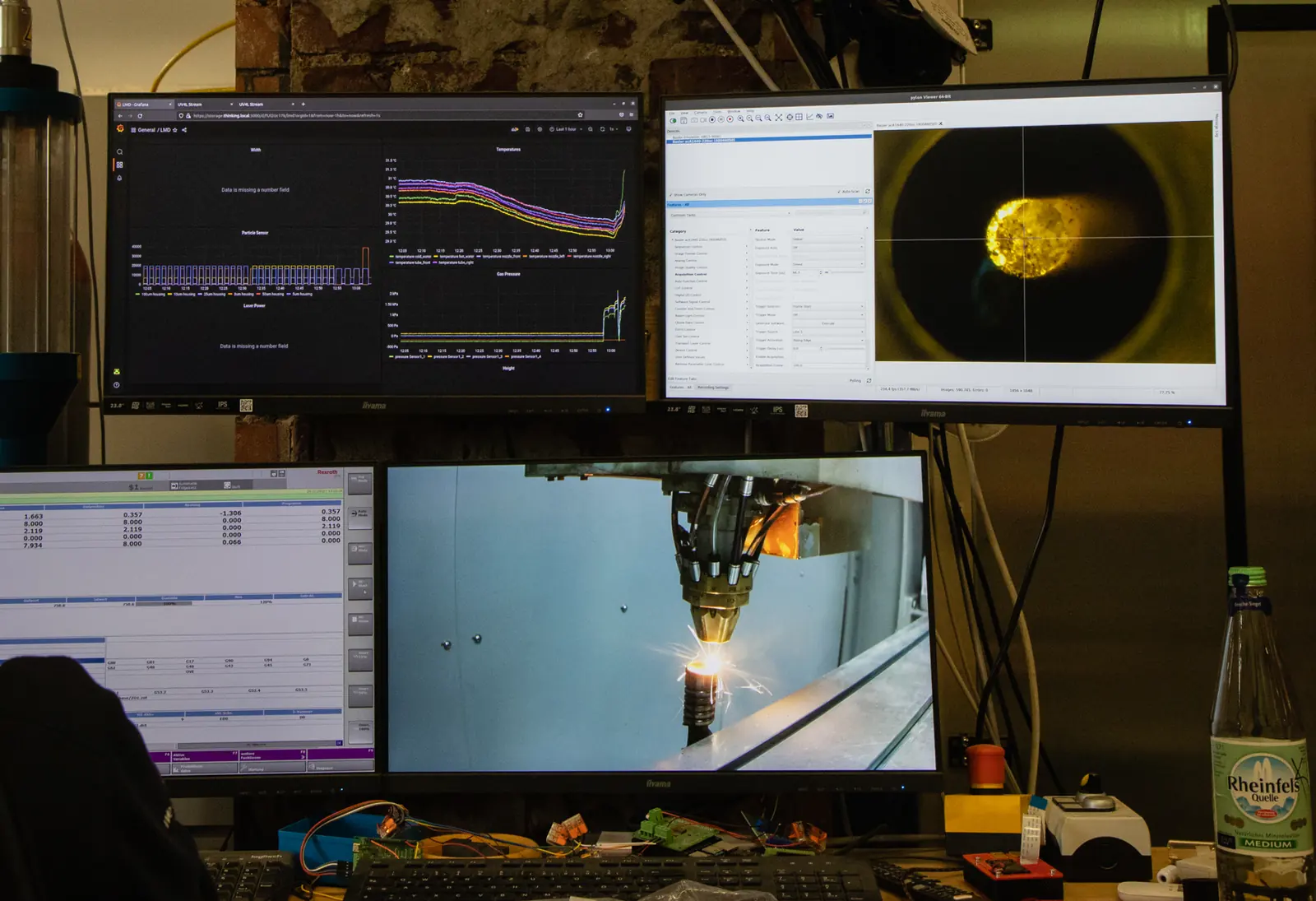
Monitoring and inspection
Image and sensor data can reveal deviations and support process development. Acceptance still requires agreed inspection methods, physical evidence and engineering responsibility.
Process selection
Exafuse will identify which process is worth assessing and what information is still missing.
Request technical reviewRecommended next steps
Continue with a relevant service, case study, technical article, FAQ or feasibility request.
Use the process comparison when part scale, local buildup, fine detail or internal channels determine the manufacturing choice.
4 more related items are available through the linked hub pages.
Match dimensional inspection, surface testing, metallography and documentation to the component function and project risk.
2 more related items are available through the linked hub pages.
Explore public work on wider deposition tracks, process monitoring and additive tooling without treating research results as production qualification.
2 more related items are available through the linked hub pages.